Follow these steps to learn how to read an input signal.
Configuration
Inputs can respond to sourcing signals (PNP, switch closure to +24) or sinking signals (NPN, switch closure to ground). Examine your sensors and determine if the controller inputs need to respond to sourcing or sinking type. It is simplest if the sensors are all the same type. If the sensors are not a all the same type contact support for additional information to support your particular sensor configuration.
If you have sinking inputs then wire "In Comm" (Input Common) to 24 volts and your sensor to the input:
If you have sourcing inputs then wire "In Comm" (Input Common) to return and your sensor to the input:
The EStop signal in the left side connector always acts like a sourcing input regardless of the wiring of Input Common. EStop must be active to permit motion.
The Modbus Motion Interface permits directing motion by performing register writes from a Modbus Master. Modbus Masters can be PLCs or PCs running third party Modbus Libraries compatible with a variety of operating system and languages.
Set Communication Parameters
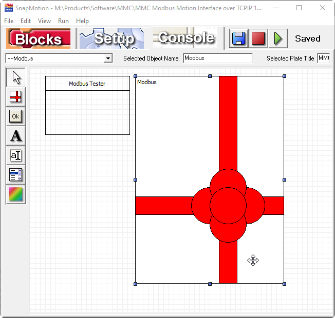
Select "File | Open Software Components..", go into the Methods Of Use directory and identify the type of Modbus Motion Interface needed. In this example we are using the 16 bit register only version. Below is the view of the TCP/IP version:
Click on the Modbus" package (ribbons and a bow) to select the package. Then click on the "Blocks" tab. This will show you the following where the IP address can be set:
By convention Modbus TCP/IP uses port 502.
Click the "Play" button and wait for the status to indicate "Running":
Use "Ping" to Confirm Network Configuration
Once the program is running we can use the "ping" command to confirm that the PC is able to connect to the controller over TCP/IP. Open a command line or PowerShell and type in the ping command:
If you do not get a ping response confirm that you have a cable plugged in and are seeing the green activity lighto on the Ethernet connector. Confirm that the PC is on the same subneet with a non-conflicting IP address.
Use Modbus Master Program to Send Commands
The following utility is provided to test the Modbus MMI. Enter the chosen IP address into the field "IP Address of the PLC" (which can also be a PC with a modbus library). On the left "Read Test" side place into the PLC Register Number the hex value $5. Place into the "Block length" field the value 1.

Now click "Read Register" and you should see prompt indicating the inputs bits for the controller. In this case input 3 is being asserted producing this result:

This response shows that register 5 contained the value 4. Bit numbers start with 1, so bit 3 corresponds to a bit encoded value of 4. The read value of 5 is the constant _InputsB1_w (Input bank 1, a word register). If a third party library was being used an API command such as this one would have achieved the same result
ModbusReadWord( System_ + _InputB1_w )Motion actions commence on the arrival of the modbus packet performing the write operation. These transactions are straightforward and deliberately controlled when when working with a modbus library and a PC program. When a PLC is acting as master there there may be numerous writes that the PLC elects to do in the course of initializing or refreshing data in the Modbus registers at it's discretion. PLCs sometimes require special treatment and an approach more analogous to a "motion block". Contact support if you are using a PLC.