Description
The 3PD Option board provides support for additional motion axes expressed as signals for use with external drives. These signals can be configured as Pulse/Direction signals or as driven quadrature signals for use with external stepper motor drivers or servo motor drivers that can accept external pulse/direction or external quadrature signals that the drive follows. Motion signals are RS422 differential outputs. If available, the quadrature format is desirable as it is more noise immune than pulse/dir however with good wiring practice either format is reliable. An input for each axis is provided and can be used for drive status or as a homing input. This input is the “+” side of a differential receiver where the “-“ side is tied to a 2 volt internal reference.
Pin Assignments
Connector on controller has female pins

Option Specifications
Signal Name Description Option Axis Input Available to be driven by external driver or sensor. This signal has a 4.7K pullup resistor to 5 volts. It is simplest for this signal to be driven low by a sinking style output. The applied voltage should not exceed 24 volts. Option Axis Step/QA+ This is the "+" side of a differential driver. The "Set Step Width" block can be used to adjust the with of the step pulse. If the source is single ended for step, with only one wire, it should be connected to this input. Option Axis Step/QA- This is the "-" side of a differential driver. This signal is connected to a 2 volt reference with a 1K ohm resistor. If the source is single ended for step, with only one wire, this pin should be left disconnected. Do not connect this signal to GND. Option Axis Dir/QB+ This is the "+" side of a differential driver. The motor reverses direction when this signal changes. If the source is single ended for direction, with only one wire, it should be connected to this input Option Axis Dir/QB- This is the "-" side of a differential driver. This signal is connected to a 2 volt reference with a 1K ohm resistor. If the source is single ended for direction, with only one wire, this pin should be left disconnected. Do not connect this signal to GND. Option /Enable This output connects to GND when the axis is enabled and is open when the motor is disabled. The output can tolerate 35 volts when in the open condition. When closed to Gnd a maximum of 30 milliamps can be driven. +5 This pin provides +5V for use with external devices that may require power to provide a signal. It is not necessary to connect +5V to this pin. Gnd This pin provides Gnd for use with external devices that may require power to provide a signal. It is not necessary to connect Gnd to this pin. Aux In One additional general purpose input is available on the option connector. This signal has a 4.7K pullup resistor to 5 volts. It is simplest for this signal to be driven low by a sinking style output. The applied voltage should not exceed 24 volts. Software Packages
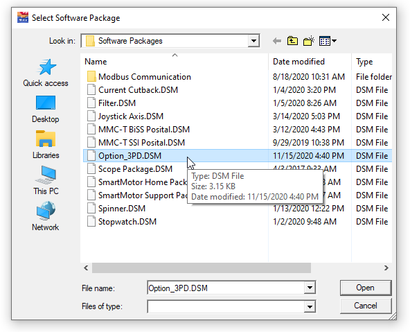
The 3PD option board is supported by the Option_3PD software package. From the console tab select the "Add Software Package" tool:

Select the Option_3PD package:
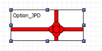
This places the Option_3PD software package into the project:
The Option_3PD software package provides two functions, one providing the axis specific inputs and the other providing the aux input value:
function Aux_Input:boolean;
Note that the Index parameter for Axis_Input is the option axis number (1, 2, or 3) and not the index of the axis in the overall axis array.
> function Axis_Input(Index:longint):boolean;Connection Table for Teknic Clearpath Drives
The following connections can be used to control a Teknic Clearpath drive configured for following mode. The High Level Feedback Signal (HFLB) is read through the axis input to obtain drive status. The "+" side of the Teknic inputs is connected to +5V in order to satisfy Teknic's voltage requirement. Connecting the "+" side of the Teknic input to the "+" side of the option's differential driver and the "-" side of the Teknic input to the "-" side of the option's differential driver would not provide sufficient voltage (as indicated in the Teknic documentation). Use the Set Step Width block to indicate step/dir format with a parameter of at least 2 microseconds.
Option Axis 1
Clearpath Pin Number Clearpath Wire Color Clearpath Signal Name Option Pin Number Option Signal Name 1 Green HLFB+ 9 Option Axis 1 Input 2 Black Input B+ 12 +5V 3 White Input A+ 12 +5V 4 Blue Enable+ 12 +5V 5 Red HLFB- 25 Gnd 6 Yellow Input B- 24 Option Axis 1 Pulse/QA- 7 Brown Input A- 23 Option Axis 1 Dir/QB- 8 Orange Enable - 22 Option Axis 1 /Enable Option Axis 2
Clearpath Pin Number Clearpath Wire Color Clearpath Signal Name Option Pin Number Option Signal Name 1 Green HLFB+ 5 Option Axis 2 Input 2 Black Input B+ 8 +5V 3 White Input A+ 8 +5V 4 Blue Enable+ 8 +5V 5 Red HLFB- 21 Gnd 6 Yellow Input B- 20 Option Axis 2 Pulse/QA- 7 Brown Input A- 19 Option Axis 2 Dir/QB- 8 Orange Enable - 18 Option Axis 2 /Enable Option Axis 3
Clearpath Pin Number Clearpath Wire Color Clearpath Signal Name Option Pin Number Option Signal Name 1 Green HLFB+ 1 Option Axis 3 Input 2 Black Input B+ 4 +5V 3 White Input A+ 4 +5V 4 Blue Enable+ 4 +5V 5 Red HLFB- 17 Gnd 6 Yellow Input B- 16 Option Axis 3 Pulse/QA- 7 Brown Input A- 15 Option Axis 3 Dir/QB- 8 Orange Enable - 14 Option Axis 3 /Enable Related Topics