Description
The Joystick Axis package takes an analog input and maps it to a useful numeric value for joystick style control. The voltage is changed so that the joystick center position is 0. The maximum deflection is +/- 1. There is also a dedband provided so that the joystick does not have to be exactly in the middle for the reported value to be 0.
Using the Joystick Axis Software Package
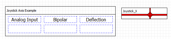
The Joystick Axis Software Package can be understood by using it in the test scaffolding program "Joystick Axis Package.DSM" project. Select "File | Open Resources" from the main menu, open the "Software Packages" directory, and choose "Joystick Axis Package.dsm". This project has three displays showing "Analog Input", "Bipolar" and "Deflection".
The package will be needing an analog input. Go to the Setup Tab and describe an analog input
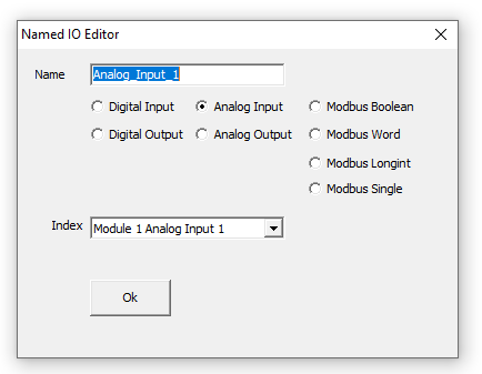
From the Console Tab select the Joystick_X package and go to the Blocks Tab to see the settings:

The first parameter identifies which analog input to use from the Setup Tab. The Center_Voltage is the voltage seen on the input when the joystick is in the neutral position. This can be read from the Analog In display. The Limit_Voltage is the voltage seen at maximum deflection. It is common for Joysticks to not be symmetrical so this limit should be set to the lesser of the two extreme voltages as seen on the Bipolar display. Joystick movements that produce centered voltages less than the deadband are disregarded. Without deadband a motor that is programmed to jog at a joystick deflection might jog very slowly if the joystick, when released, did not move back to the exact center.
The Joystick Axis package has two outputs. One output is Bipolar_Voltage that contains the centering and deadband effects. This output is useful for finding a good Limit_Voltage. Deflection reads the bipolar voltage, limits the voltage with the Limit_Voltage and scales the result to be in the range of -1 to 1.

If the direction is wrong the Set Coordinate Inversion block can be used to reverse it.
Adding the Package
Open the current work-in-progress project, or select File | New Project. Select the Add Software Package Tool:
Choose the Joystick Axis Package project and the Joysitck Axis will be placed into the currently open project. Name the package as appropriate for its purspose. For additional joystick directions add additional Joystick Axis packages.
Joystick Wiring
Joysticks are provided with flying leads. The leads of the joystick cable are numbered as follows:
Description Wire Number Typical Connection GND 1 GND on power supply or Encoder Connector VCC 2 5V Out on Encoder Connector or VCC3.3 connection on MMC-3T X Signal 3 Available Analog Input Y Signal 4 Available Analog Input Z Signal 5 Available Analog Input Switch 1 6 Available Digital Input Switch 2 7 Opposite of In Common (If In Common is Logic Power then GND. If In Common is GND then Logic Power)