Preparing the OEM-2T for use with the Modbus Motion Interface
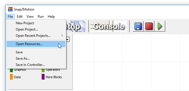
For methods of use besides Snap2Motion and MotionLib it is necessary to place in the controller an application program that responds to that method. From a blank Snap2Motion project click the green "Play" button and run an empty application. This establishes a connection and Snap2Motion is aware of what controller it is connected to. Once Snap2Motion recognizes the controller the resources it provides will be specific to that controller. After connecting select "File | Open Resources..."
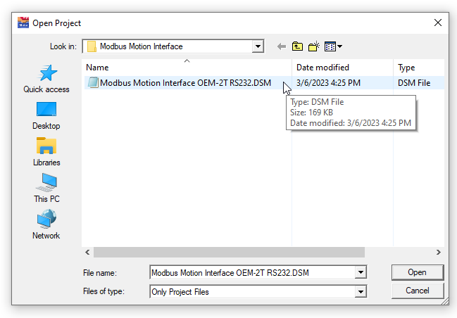
Open the "Methods Of Use" folder, double click into the "Modbus Motion Interface" directory, and select
This project is a "test scaffold" that can be used to run the Modbus Motion Interface on the controller and inspect some values. It's also possible to use the Console Tab "+" button to add the Modbus Motion Interface to a project that has already been developed. Click the Console tab and select the "ModbusMotionInterface" software package so that it has the 8 handles.
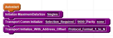
Select the "Blocks" tab to see the setup choices.
The Maximum Data Size field allows the Modbus Motion Interface to accomodate the limitations of the host.
Some hosts only support 16 bit words and no floating point. To use a host with this limitation select "Words". The controller will then use that sized data type for all the commands. Some hosts support single precision data commonly referred to as "floats". For this host select "Singles". The controller will downgrade any commands that normally use double precision values to use single precision. Other hosts support double precision floating point data. For this case select "Doubles". This provides the maximum resolution but is generally not needed.
The next field indicates what communication port to use.
For the OEM-2T select either "OEM_2T_Port_1" (the plug adjacent to the power connector) or "OEM_2T_Port_2". If the controller is commanding responder controllers over a network then port 1 is committed to that purposes so the Modbus Motion Interface should connect to port 2. If using port 2 it is best to run no faster than 9600 baud. The parity can also be selected.
The last field indicates the address offset.
The Modbus protocol specifies that addresses are numbered 1 to N however the actual data in the payload of the Modbus frame conveys the address information as 0 to N-1. Some hosts follow the specification and indicate an address in the range 1 to N. Other hosts use the payload convention. Select the choice that reflects the host convention so that it matches.
Despite being a "standard" there are enough differences in specification interpretation that it is necessary to confirm that the controller conventions match the host. To help check there are some alignment values provided. These are modbus register locations in the controller with predefined known values. If the host checks these locations and finds the expected values then the controller matches the host. The first alignment to check is the Word Alignment Check Constant. If the proper value is not read then adjust the Address Offset in the Modbus Motion Interface configuration blocks.
After succeeding with words, and if floating point values are to be used, confirm that the Single Alignment Check Constant properly works. If a different value is reported it is likely because the word order being used by the host is different from the controller. This is often referred to as "Endianess", either "Big Endian" (high word is at the lower address of the register pair representing the value) or "Little Endian" (high word is at the higher address of the register pair). Investigate if the host has the ability to change the Endianess. If not contact support for assistance. If doubles are to be used read the Double Alignment Check Constant.