Follow these steps to setup the controller and achieve initial motion.
Wiring
Connect the motor leads from your bipolar motor as shown on the label for Mtr 1. The Mtr 1 plug is the lower plug.
Wire a 24 volt power supply to the controller. The power plug is the upper plug. Supply return goes to the GND pin. Positive 24 volts goes to Logic Pwr, Mtr Pwr, and In Common.
Place a loopback cable as shown on the side connector. This satisfies the EStop circuit which is necessary to permit motion.
Apply power to the controller. The green "heartbeat" LED should start blinking after about 3 seconds . The heatbeat LED needs to be blinking before the controller will respond to software. If you encounter a problem the first question support will ask will likely be "Is the heartbeat LED still blinking? Was there any deviation to the blink pattern during the problem?".
The Modbus Motion Interface permits directing motion by performing register writes from a Modbus Master. Modbus Masters can be PLCs or PCs running third party Modbus Libraries compatible with a variety of operating system and languages.
Set Communication Parameters
Select "File | Open Software Components..", go into the Methods Of Use directory and identify the type of Modbus Motion Interface needed. In this example we are using the 16 bit only version. Below is the view of the TCP/IP version:
Click the "Play" button and wait for the status to indicate "Running":
Use "Ping" to Confirm Network Configuration
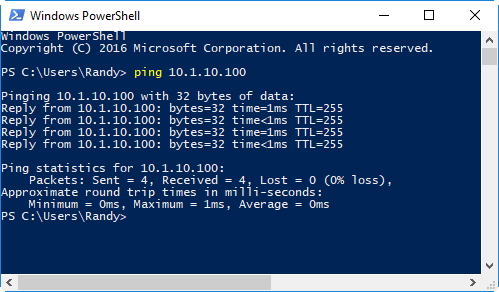
Once the program is running we can use the "ping" command to confirm that the PC is able to connect to the controller over TCP/IP. Open a command line or PowerShell and type in the ping command:
If you do not get a ping response confirm that you have a cable plugged in and are seeing the green activity lighto on the Ethernet connector. Confirm that the PC is on the same subneet with a non-conflicting IP address.
Use Modbus Master Program to Send Commands
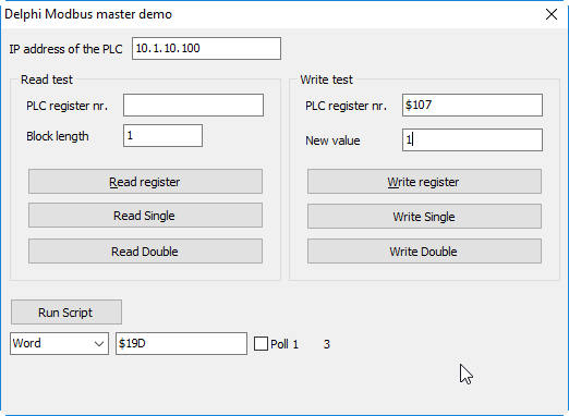
The following utility is provided to test the Modbus MMI. Enter the chosen IP address into the field "IP Address of the PLC" (which can also be a PC with a modbus library). Place into the PLC Register Number the hex value $107. Please into the New Value field the value 1.
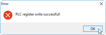
Now click "Write Register" and you should see a confirming prompt indicating the write has occurred:
The motor should now be holding position. The address of $107 corresponds to the value produced by adding together the MMI constants "Axis_1_" and "_MotorOn_w". The value "1" corresonds to "true" or "on". In a third party library this might be expressed as
ModbusWriteWord( Axis1_ + _MotorOn_w, 1 )Now write the value of 1 to address $181:
In a third party library this might be expressed as:
ModbusWriteWord( Axis1_ + _BeginMoveBy_w, 1 )This should cause the motor to turn one rotation.
Motion actions commence on the arrival of the modbus packet performing the write operation. These transactions are straightforward and deliberately controller when when working with a modbus library and a PC program. When a PLC is acting as master there there may be numerous writes that the PLC elects to do in the course of initializing or refreshing data in the Modbus registers at it's discretion. PLCs sometimes require special treatment and an approach more analogous to a "motion block". Contact support if you are using a PLC.